UPDATE 7/25/2021
New kits now have all the 0805 SMT resistors pre-installed on the PCB. Making assembly much easier.
UPDATE 5/11/2021
I’ve received all the parts necessary to build more kits and they are now available again.
Please visit my store if you would like to buy a Pi-KVM ATX Controller kit.
Here are my ebay listing if you would rather use ebay.
https://www.ebay.com/itm/265118320633
https://www.ebay.com/itm/265214220357
Pi-KVM is a wonderful and fully functional KVM that runs on the Raspberry PI. However, to fully utilize the remote ON/OFF/REBOOT feature of Pi-KVM, you’ll need to breadboard your own ATC controller. I have created a custom PCB so that you don’t need to use a breadboard. It also has the added advantage of being more compact and secure. You can purchase the kit here that includes the PCB and all the components necessary to assemble your own ATX controller board.
Assembly steps for the Pi-KVM ATX controller board
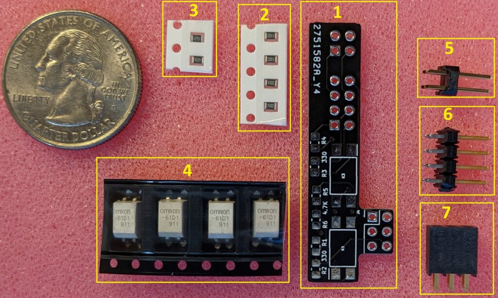
Parts list:
- Custom ATX Controller PCB
330 ohm 0805 SMT resistor(pre-installed on the PCB)4.7K ohm 0805 SMT resistor(pre-installed on the PCB)- Omron G3VM-61D1 MOSFET relay
- 2×2 0.100″ (2.54mm) pitch square post terminal
- 2×4 0.100″ (2.54mm) pitch square post terminal
- 2×3 0.100″ (2.54mm) pitch square post socket
— Step 1 — (All kits now have SMT resistors pre-installed, skip this step)

Solder the for 330 ohm (part 2) resistors to the PCB at R1, R2, R3 and R4 as shown in the above picture. Solder the two 4.7k ohm resistors (part 3) at R5 and R6.
— Step 2 —
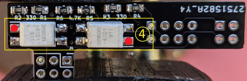
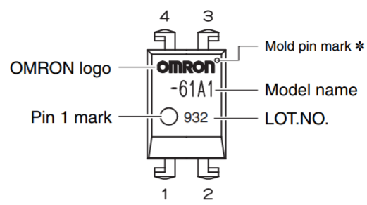
Solder the Omron relay (part 4) to K1 and K3. Note the Pin 1 marker in the picture. The two relays are not oriented the same.
— Step 3 —

Flip the PCB around and solder the Omron relay (part 4) to K2 and K4. Note the Pin 1 marker in the picture. The two relays are not oriented the same.
— Step 4 —
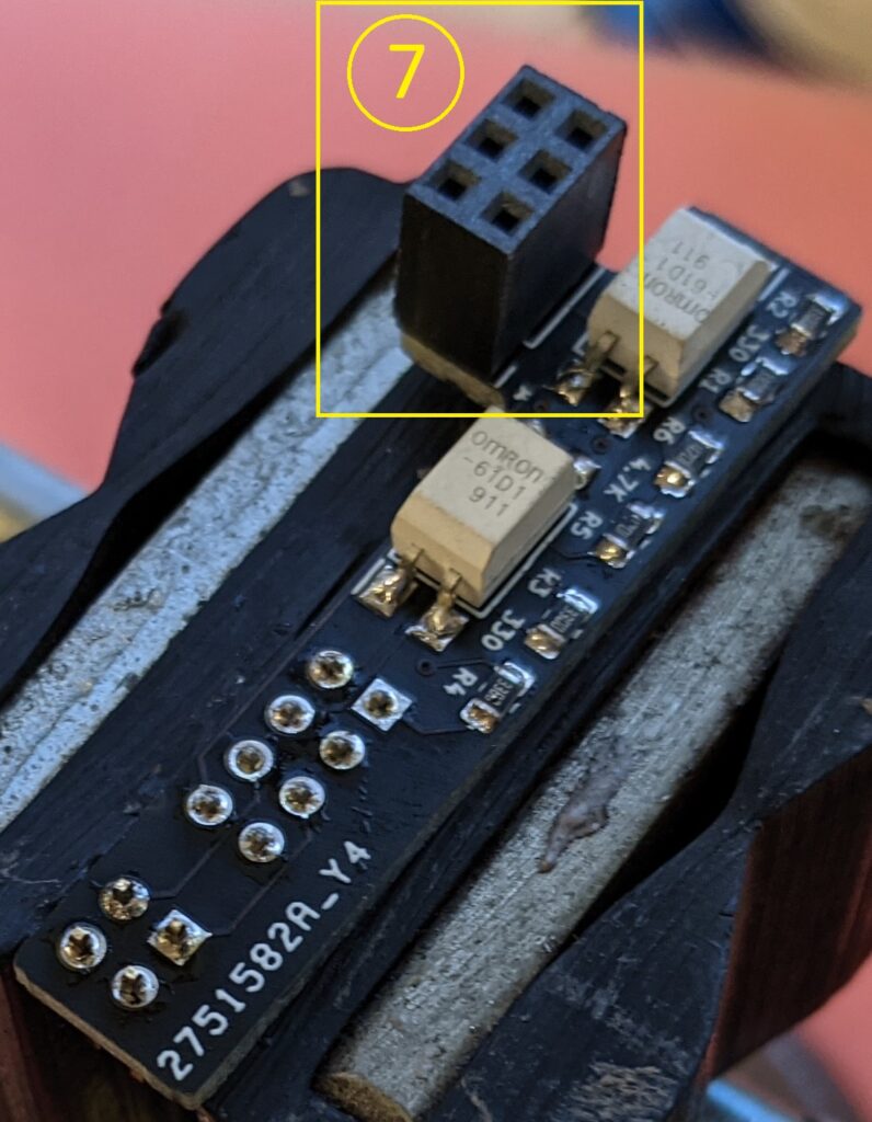
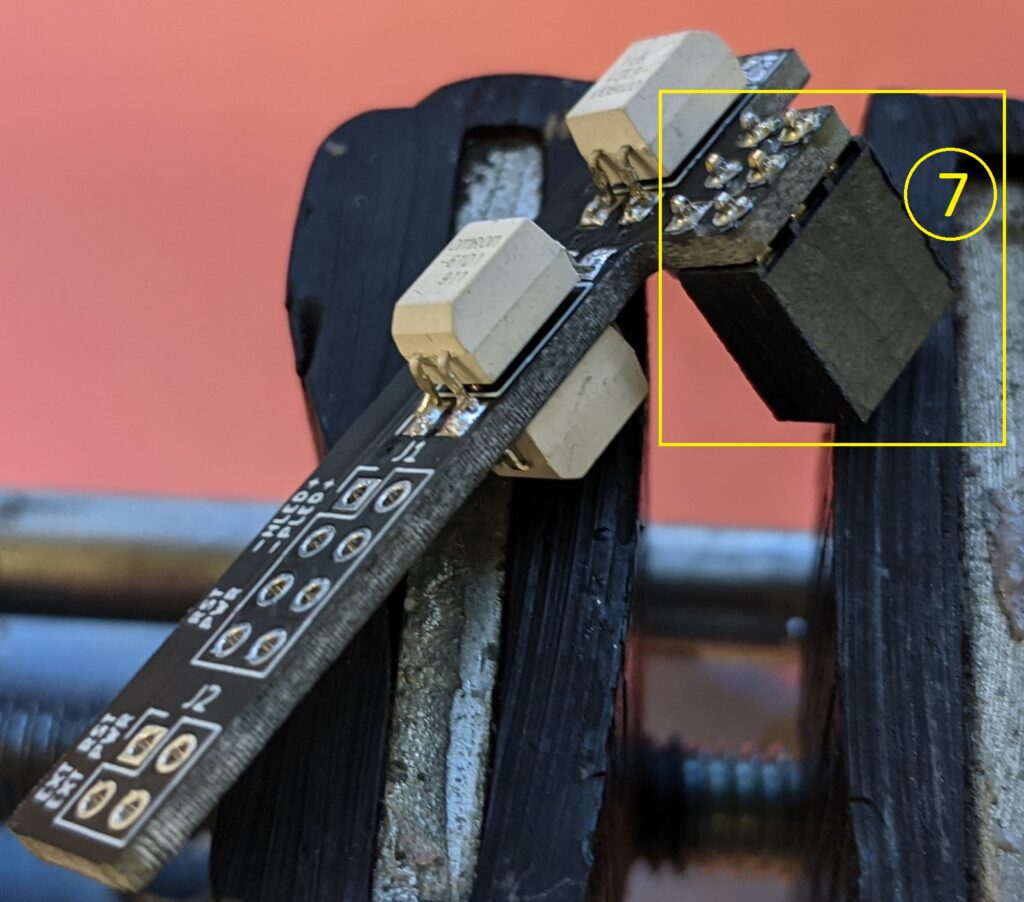
Install the square post socket (part 7) to J4. Note the orientation of the socket relative to the PCB. The socket itself should be on the same side of the PCB as the resistors.
— Step 5 —
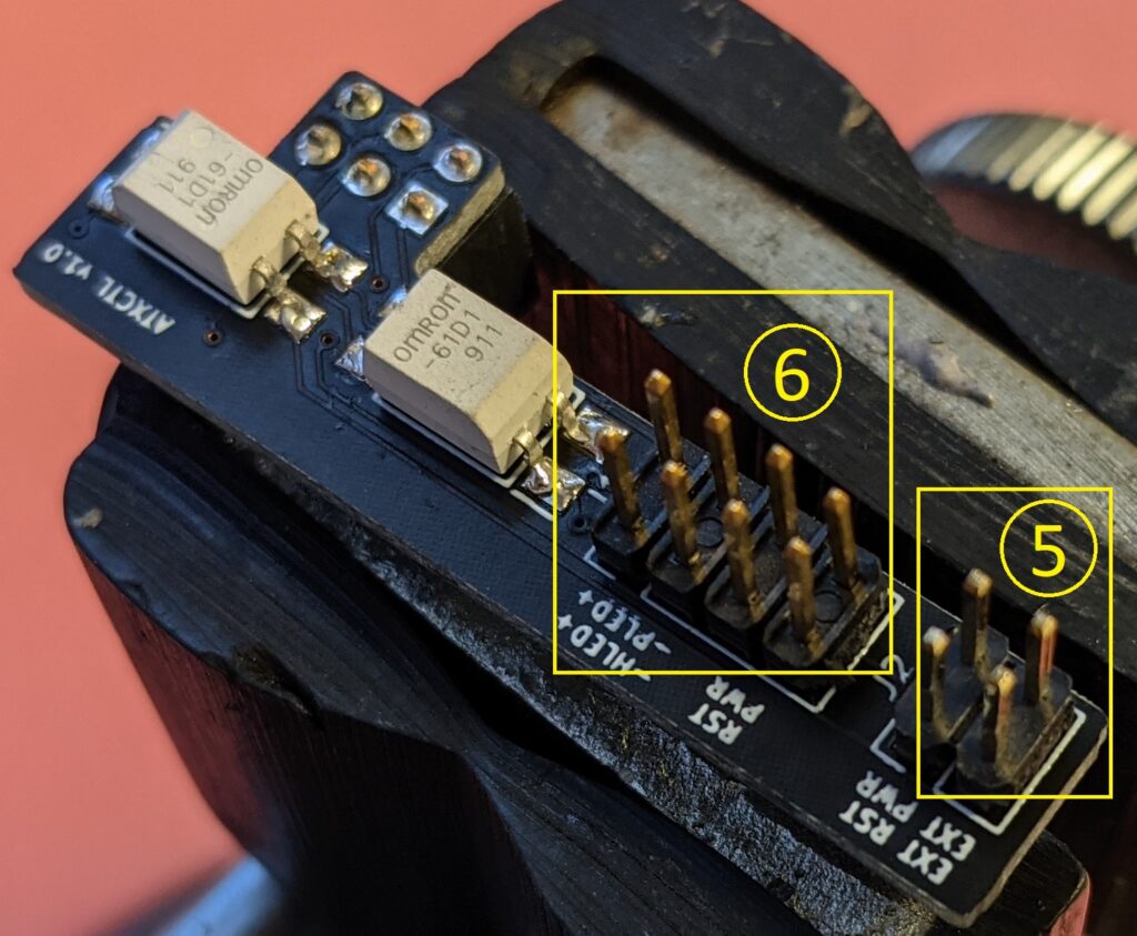
Install the 2×2 square post terminal (part 5) to J2 and the 2×4 square post terminal (part 6) to J1. Note the orientation of the terminal relative to the PCB. The terminals should be on the side without the resistors.
The ATX controller board is now fully assembled.
Install ATX controller to Raspberry PI
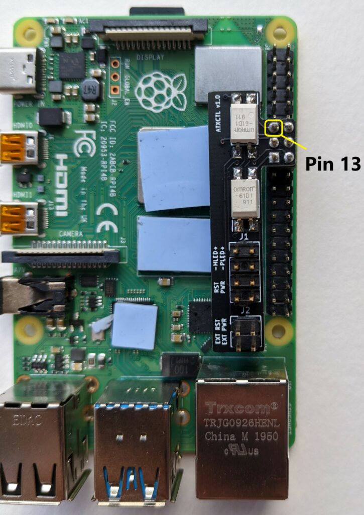

As you look down on the ATX controller PCB, the top-left pin should be installed onto pin 13 of the Raspberry Pi. Looking from the side, the ATX controller PCB should be installed starting at the 7th row.
ATX control pinout
The ATX control pins (J1) is mapped the same as the Intel Desktop boards. There isn’t a standard for the ATX front panel pinout, but the Intel pinout is used on a lot of desktop motherboard.
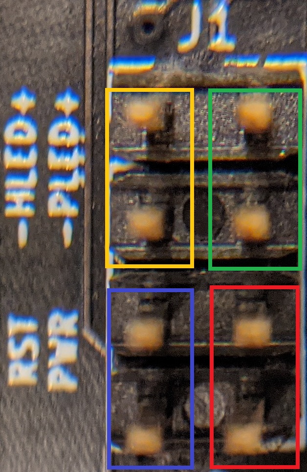
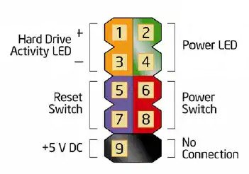
Check with your motherboard manual for the front panel pinout. Use the 2×1 ribbon cables and connect each function on J1 to the appropriate location on the motherboard’s front panel header.

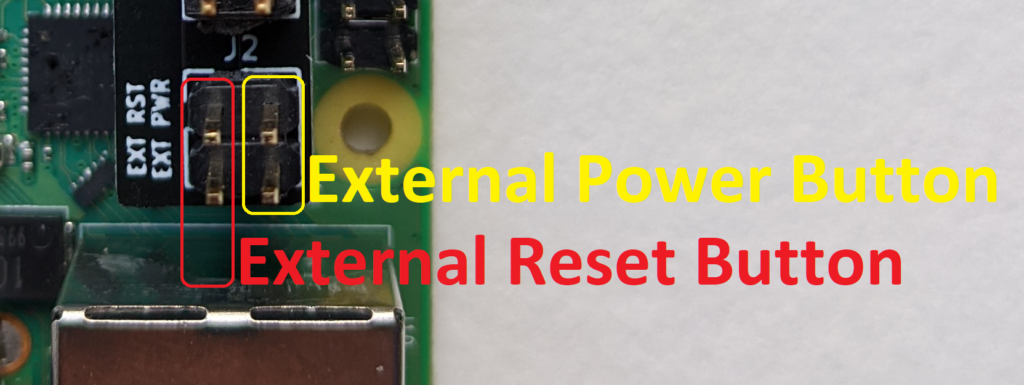
Optional External Power and Reset button
The ATX controller board allows for the use of an external power and reset button. The controller board pass this signal through to the motherboard so that you can still use your case’s power and reset button in addition to the controls from Pi-KVM. This step is optional and does not affect the operation of the Pi-KVM.
Fully connected system


ATX Controller PCB schematic
atxctlATX Controller PCB gerbers
Please visit my store if you would like to buy a Pi-KVM ATX Controller kit.
Here are my ebay listing if you would rather use ebay.
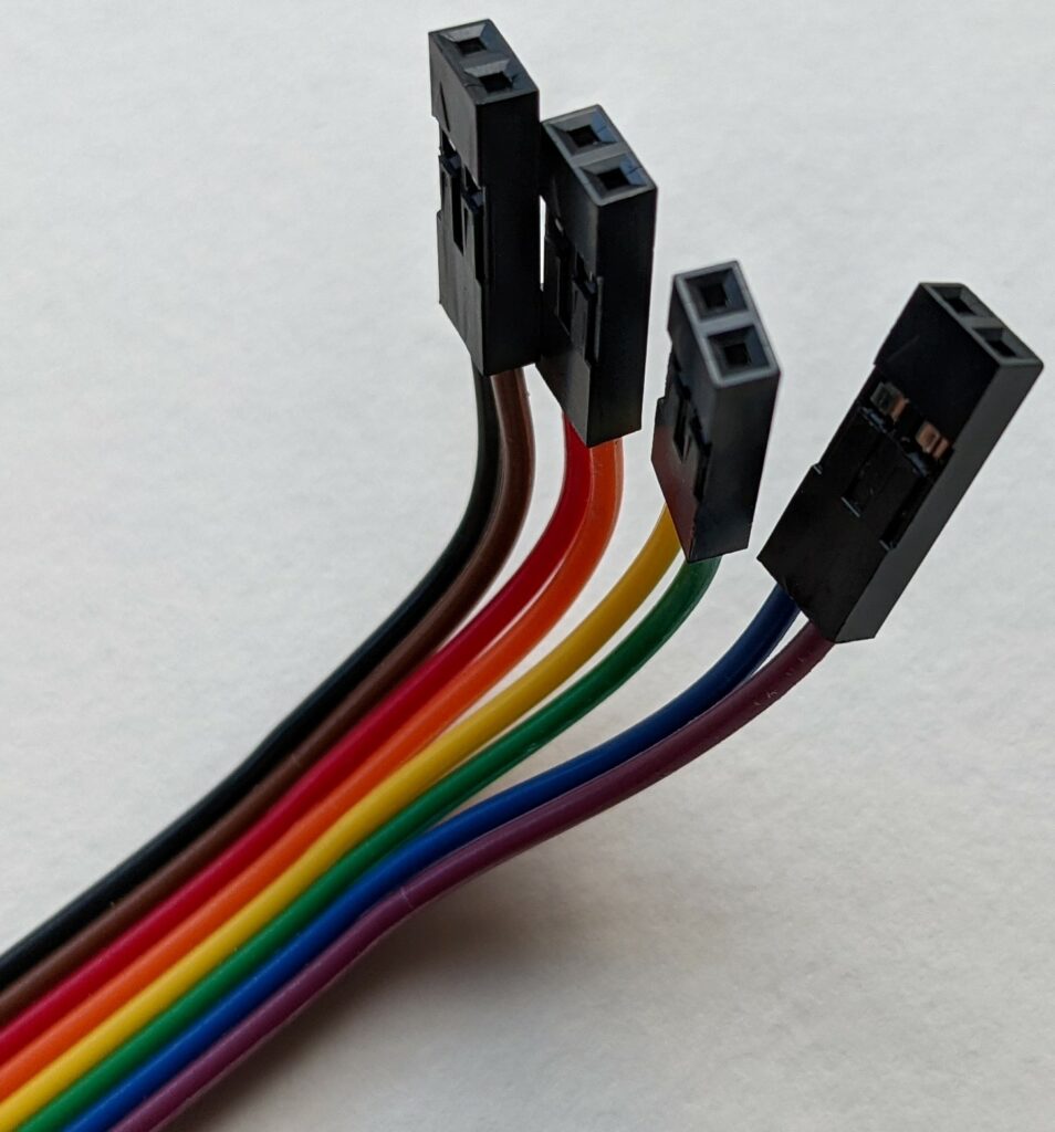
Where can I get the split 2×1 connectors shown here?
I include a set of four 2×1 cables with the atx controller kit.